Location: University of Toronto
(2023)
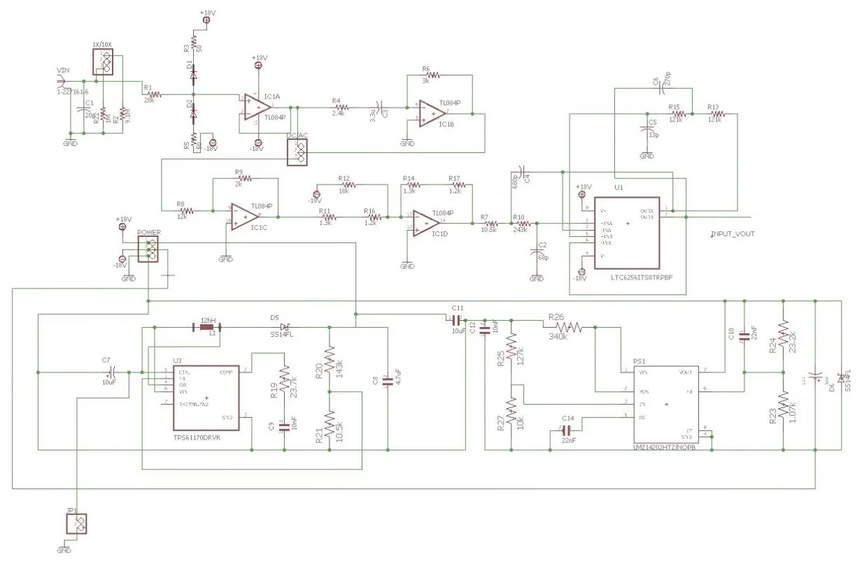
Circuit Design Project 1
Description:
Input Voltage: The circuit accepts a varying voltage signal ranging from -15V to +15V.
Output Voltage: The output voltage ranges from 0V to 5V, maintaining the same DC offset of 2.5V.
Mode Selection: The design includes a mechanical switch to toggle between:
1X Mode and 10X Mode
AC Coupling Mode and DC Coupling Mode
Frequency Response:
The design attenuates frequencies up to and including 20 kHz.
It achieves an attenuation of at least -20 dB at 50 kHz.
Function: Converts one DC voltage to another, potentially with different polarity.

